
Table of Contents
Wifi / WLan Kommunikation mit Arduino
Im folgenden zeigen wir anhand von Beispielen verschiedener Module, wie ein Arduino über ein Wireless LAN kommunizieren kann. Es existieren eine Vielzahl von Modulen, die eine WLan Anbindung für Arduino ermöglichen.
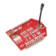
RN-XV WiFly Modul
Als erstes haben wir uns das RN-XV WiFly Modul von Roving Networks vorgenommen, dieses bietet einiges an Funktionalität für den Preis:
Konfiguration WiFly Modul
Das Modul kommt vorteilhafterweise gleich mit einer integrierten Antenne und ist in jedem XBee Sockel einsetzbar.
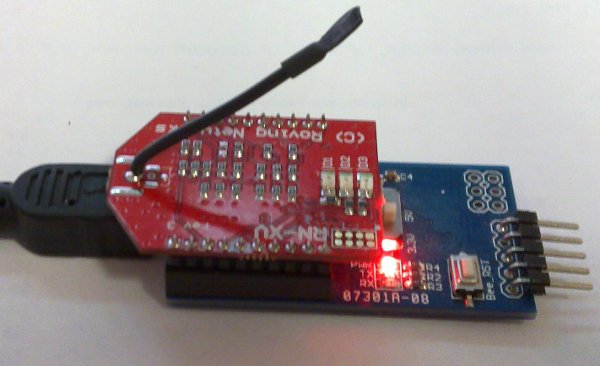
Um das Modul zu konfigurieren wird eine serielle Verbindungen mit z.B. einem Foca oder UartSBee eingesetzt. Natürlich geht das auch mit Shields die eine direkte Kommunikation mit dem XBee Modul erlauben, wie z.B. dem Itead XBee Shield. Die Konfiguration selbst geschieht mit einfachen Kommandos, welche über die serielle Schnittstelle abgesetzt werden. Es gilt dabei zu beachten, dass das WiFly Modul zwei exklusive Betriebsmodi für seine Schnittselle kennt:
- command mode
- data mode
Nach dem Start befindet sich das WiFly im data mode, zum Umschalten in den command mode wird standardmässig folgende Zeichenfolge gesendet (konfigurierbar):
$$$
Dabei sollte nach dem letzten $-Zeichen für min. 250ms kein anderes Zeichen gesendet werden, da die Drahtlos-Fliege dies sonst als Teil eines zu übermittelnden Datenpakets ansieht und nicht in den command mode wechselt. Ist der Wechsel in den command mode erfolgreich, quittiert das die Fliege mit einem Prompt der die Firmware Version enthält:
<2.32>
Standardmässig ist das WiFly Modul auf 9600 (8N1) eingestellt, dies kann jedoch im Konfigurationsmodus ebenfalls geändert werden.
Ist die Verbindung mit einem Terminalprogramm (Achtung: der Serial Monitor von Arduino eignet sich dazu NICHT) erstellt, und mit $$$ in den command mode gewechselt, kann ein Modul mit z.B. folgenden Befehlen einfach an eine WPA2-PSK gesicherters WLan angebunden werden: Erfolgreiche Kommandos werden vom Modul mit dem String AOK beantwortet.
set wlan ssid IHRE_WLAN-SSID
set wlan phrase Ihr-WPA2-preshared_Key
set wlan rate 0
set ip dhcp 1
set comm idletimer 3
set ip host 10.10.200.3
set ip remote 8000
join IHRE_WLAN-SSID
Jedes Kommando sollte jeweils mit AOK quittiert werden, dann wurde dies erfolgreich ausgeführt, d.h. das sieht dann etwa so aus im Terminal:
<2.32> set wlan ssid IHRE_WLAN-SSID
AOK
<2.32> set wlan phrase Ihr-WPA2-preshared_key
AOK
<2.32> set wlan rate 0
AOK
<2.32> set ip dhcp 1
AOK
<2.32> set comm idletimer 3
AOK
<2.32> set ip host 10.10.200.3
AOK
<2.32> set ip remote 8000
AOK
<2.32> join IHRE_WLAN-SSID
DeAuth
Auto-Assoc IHRE_WLAN-SSID chan=3 mode=WPA2 SCAN OK
Joining IHRE_WLAN-SSID now..
<2.32> Associated!
DHCP: Start
DHCP in 15ms, lease=1200s
IF=UP
DHCP=ON
IP=10.10.200.139:2000
NM=255.255.255.0
GW=10.10.200.1
<2.32>
Erklärungen zur Konfiguration
Das Modul ist nun am Netzwerk angemeldet und hat eine IP-Adresse vom DHCP Server bezogen (10.10.200.139).
Das WiFly hört auf Port tcp/2000 und verbindet sich bei Erhalt des open-Befehls mit dem Server bei 10.10.200.3 auf Port tcp/8000.
Der Befehl set comm idletimer 3 bewirkt, dass das Modul offene TCP-Verbindungen nach 3s ohne Datenverkehr wieder schliesst und damit für neue Verbindungen bereit ist.
Mit dem Befehl set wlan rate 0 wir die Datenrate auf 1Mbit/s gesetzt, dies ausreichend für die meisten Zwecke und erhöht die Zuverlässigkeit/Reichweite des Moduls.
Mehr Informationen zu den Konfigurationsmöglichkeiten finden Sie im aktuellen WiFly User Manual.
Konfiguration speichern
Wichtig: Die Konfiguration ist nun noch nicht auf dem WiFly Modul dauerhaft gespeichert, dies geschieht erst mit dem Kommando save:
<2.32> save
AOK
Es ist auch möglich, die Konfiguration unter einem eigenen Namen zu speichern und diese wiederum mit dem Befehl load <config-name> zu laden:
<2.32> save HOMENET
AOK
<2.32> load HOMENET
AOK
Factory Reset
Um die Default Werte nach Auslieferung des Moduls wieder herzustellen kann der Befehl factory RESET verwendet werden.
Konfiguration des WiFly Moduls aus dem Arduino Sketch
Manchmal will man vermeiden des Modul je wieder ausbauen zu müssen nur weil z.B. das WLAN Passwort geändert hat. In so einem Fall kann man mit einigen Tricks das WiFly Modul auch über Software Serial beim Start konfigurieren.
Fallstricke
In unseren Tests hat sich gezeigt, dass bei der Verwendung von SoftwareSerial bei 9600 immer wieder Zeichen verloren gehen und dies einen zuverlässigen Start verunmöglicht. Mit der AltSoftSerial von PJRC dagegen hatten wir sofort sehr gute Resultate und nach etwas Feintuning der Delays nun sogar äusserst zuverlässigen Betrieb mit Adhoc Konfiguration aus dem Arduino Sketch. Einziger Nachteil dabei ist, dass die zu verwendenden Pins fest vorgegeben sind (TX: 9, RX: 8) und mit der Verwendung der Library kein PWM mehr auf Pin 10 zur Verfügung steht.
Beispielcode
Konfiguration WiFly Moduls aus der setup() Funktion heraus:
# Konfiguration eines WiFly Moduls 'on-the-fly'
# 2013 boxtec internet appliances

#include <AltSoftSerial.h>
// TX: 9, RX: 8, Unusable PWM: 10
// see http://www.pjrc.com/teensy/td_libs_AltSoftSerial.html

#define CMD_DELAY 540
#define ESC_DELAY 685

AltSoftSerial mySP;

void setup() {
  mySP.begin(9600);
  delay(CMD_DELAY);
  sendESC("$$$", ESC_DELAY);
  sendCMD("reboot",1600);
  sendCMD("factory RESET", 1800);
  sendESC("$$$", ESC_DELAY);
  sendCMD("set wlan rate 0", CMD_DELAY);
  sendCMD("set wlan ssid IHRE-WLAN-ID", CMD_DELAY);
  sendCMD("set wlan phrase Ihr-WLAN-Passw0rt", CMD_DELAY);
  sendCMD("set ip dhcp 1", CMD_DELAY);
  sendCMD("set comm idletimer 1", CMD_DELAY);
  sendCMD("set comm remote 0", CMD_DELAY);
  sendCMD("set comm match 13", CMD_DELAY);
  sendCMD("set ip host 192.68.1.100", CMD_DELAY);
  sendCMD("set ip remote 8000", CMD_DELAY);
  sendCMD("join IHRE-WLAN-ID", 6000);
  sendCMD("exit",100);
}

void loop() {
  //
}

void sendESC(char esc[], int _delay) {
  mySP.print(esc);
  delay(_delay);
}

void sendCMD(char cmd[], int _delay) {
  mySP.println(cmd);
  delay(_delay);
}
Praktische Anwendung des WiFly mit Arduino
Wir bauen uns einen Kontroller welche in der Garagenbox angebracht wird, Ziele sind folgende:
- Messung der Aussentemperatur mit 2 DS18B20 Aussenfühler
- Messung der Luftfeuchtigkeit (und Innentemperatur) mit DHT22
- Steuerung eines Lüfters zur Entfeuchtung bei Kondenswasser
- Erfassen von Bewegungen
- Schalten eines 12V LED Streifens zur automatischen Beleuchtung
- Erreichbarkeit und Abfrage der Messwerte und Zustände über Wireless LAN
- Möglichkeit Grenzwerte für die Lüftreglung remote zu setzen
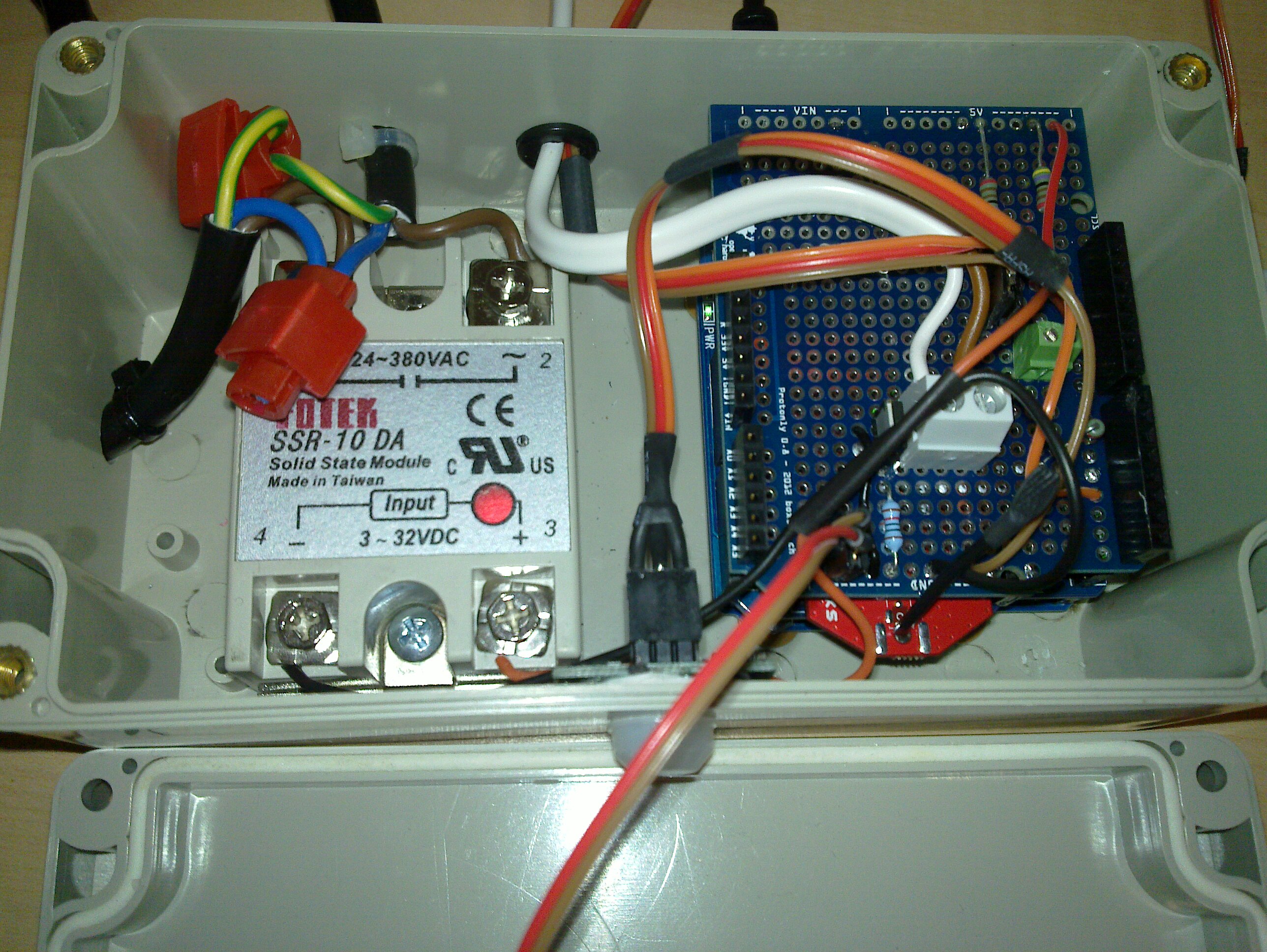
Unser kleines Projekt umfasst:
- ein blaues LED mit Vorwiderstand für I-Effekt und weil wir es können und noch PWM I/O frei hatten

- Etwas Flachbandkabel und Lötzinn
- Ca. 1m Netzkabel 3-adrig (min. 1mm2) sowie eine 230V Stecker und 230V Buchse
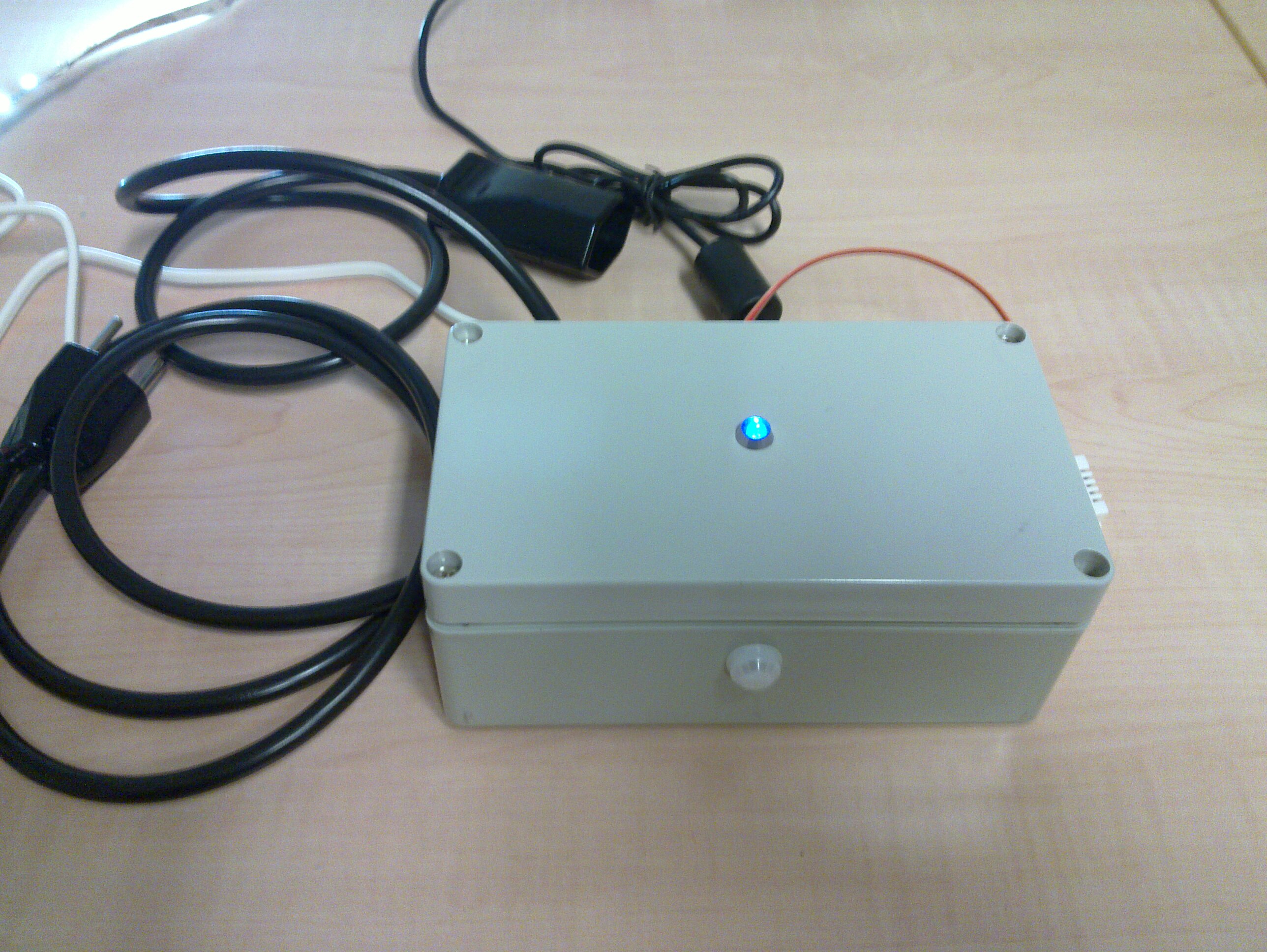
Das fertige Projekt
Der Arduino Sketch
// Copyright (c) 2002-2012 boxtec internet appliances <playground@boxtec.ch>
//
// All rights reserved.
//
// Redistribution and use in source and binary forms, with or without
// modification, are permitted provided that the following conditions
// are met:
// 1. Redistributions of source code must retain the above copyright
//    notice, this list of conditions and the following disclaimer.
// 2. Redistributions in binary form must reproduce the above copyright
//    notice, this list of conditions and the following disclaimer in the
//    documentation and/or other materials provided with the distribution.
// 3. The name of the author may not be used to endorse or promote products
//    derived from this software without specific prior written permission.
//
// THIS SOFTWARE IS PROVIDED ``AS IS'' AND ANY EXPRESS OR IMPLIED WARRANTIES,
// INCLUDING, BUT NOT LIMITED TO, THE IMPLIED WARRANTIES OF MERCHANTABILITY
// AND FITNESS FOR A PARTICULAR PURPOSE ARE DISCLAIMED.  IN NO EVENT SHALL
// THE AUTHOR BE LIABLE FOR ANY DIRECT, INDIRECT, INCIDENTAL, SPECIAL,
// EXEMPLARY, OR CONSEQUENTIAL DAMAGES (INCLUDING, BUT NOT LIMITED TO,
// PROCUREMENT OF SUBSTITUTE GOODS OR SERVICES; LOSS OF USE, DATA, OR PROFITS;
// OR BUSINESS INTERRUPTION) HOWEVER CAUSED AND ON ANY THEORY OF LIABILITY,
// WHETHER IN CONTRACT, STRICT LIABILITY, OR TORT (INCLUDING NEGLIGENCE OR
// OTHERWISE) ARISING IN ANY WAY OUT OF THE USE OF THIS SOFTWARE, EVEN IF
// ADVISED OF THE POSSIBILITY OF SUCH DAMAGE.
//
// --------------------------------------------------------------------------
//  $Id: wifi_sensor.ino,v 1.10 2013-01-01 10:21:34 obiwan Exp $
// --------------------------------------------------------------------------
//
// Written for Arduino IDE 1.0
//
// LEDs:
// Power (fade)
// SSR State
// Light State
// Motion Detect
//
// PINS:
// PIR    : 3
// LIGHT  : 5
// LED-PWR: 6
// SSR    : 11
// DHT    : 12
// Onewire: 13
//


#include <AltSoftSerial.h>
// TX: 9, RX: 8, Unusable PWM: 10
// see http://www.pjrc.com/teensy/td_libs_AltSoftSerial.html
#include <OneWire.h>
#include <DallasTemperature.h>
#include <dht.h>

// DEBUGGING (enable to debug)
//#define SDBG

#define BUF_SIZE 255
#define ESCAPE_CHAR '*'
#define ONE_WIRE_BUS 13
#define DHT_PIN 12
#define SSR_PIN 11
#define PIR_PIN 3
#define LIGHT_PIN 5
#define LED0_PIN 6
#define CMD_DELAY 540
#define ESC_DELAY 685
#define PIR_DELAY 50000
#define LOOP_IX_MAX 60
#define INOUT_DIFF 3
#define LIGHT_INCR 16
#define LIGHT_DECR 5

#define TEMPERATURE_PRECISION 9
#define TEMPERATURE_REFRESH 5000
#define REGULATOR_REFRESH 6000
#define LED_REFRESH 75

int buffer_pos = 0;
byte led0_pwm = 0;
int led0_pwm_incr = 50;
char open_cmd[6] = "OPEN";
char close_cmd[6] = "CLOS";
float cur_temp;
float cur_hyg;
float temperature0;
float temperature1;
float target_temp = 31;
float target_hyg = 48;
volatile long pir_timer = 0;
volatile int light_level = 0;
long loop_start = 0;
long loop_duration_avg = 500;
int loop_ix = 1;
long loop_sum = 10000000;
int pwm_incr = 50;

OneWire oneWire(ONE_WIRE_BUS);
DallasTemperature sensors(&oneWire);
DeviceAddress outside0Temp, outside1Temp;
AltSoftSerial mySP;
dht DHT;


//
// SETUP
//
void setup() {
  #ifdef SDBG
    Serial.begin(57600);
    while (!Serial) {
      ; // wait for serial port to connect. Needed for Leonardo only
    }
  #endif

  analogWrite(LED0_PIN, 200);
  pinMode(SSR_PIN, OUTPUT);
  pinMode(PIR_PIN, INPUT);
  analogWrite(LIGHT_PIN, 8);
  digitalWrite(SSR_PIN, LOW);
  mySP.begin(9600);
  delay(CMD_DELAY);
  sendESC("$$$", ESC_DELAY);
  sendCMD("reboot",1600);
  sendCMD("factory RESET", 1800);
  readData();
  sendESC("$$$", ESC_DELAY);
  sendCMD("set wlan rate 0", CMD_DELAY);
  sendCMD("set wlan ssid IHRE-WLAN-ID", CMD_DELAY);
  sendCMD("set wlan phrase Ihr-WLAN-Passw0rt", CMD_DELAY);
  sendCMD("set ip dhcp 1", CMD_DELAY);
  sendCMD("set comm idletimer 1", CMD_DELAY);
  sendCMD("set comm remote 0", CMD_DELAY);
  sendCMD("set comm match 13", CMD_DELAY);
  sendCMD("set ip host 192.68.1.100", CMD_DELAY);
  sendCMD("set ip remote 8000", CMD_DELAY);
  sendCMD("join IHRE-WLAN-ID", 6000);
  readData();
  sendCMD("exit",100);

  sensors.begin();
  // set the resolution to 12 bit
  sensors.setResolution(outside0Temp, TEMPERATURE_PRECISION);
  sensors.setResolution(outside1Temp, TEMPERATURE_PRECISION);

  #ifdef SDBG
    Serial.print("Status PIR Sensor: ");
    Serial.println(digitalRead(PIR_PIN));

    Serial.print("Device 0 Resolution: ");
    Serial.print(sensors.getResolution(outside0Temp), DEC);
    Serial.println();

    Serial.print("Device 1 Resolution: ");
    Serial.print(sensors.getResolution(outside1Temp), DEC);
    Serial.println();

    Serial.print("Found ");
    Serial.print(sensors.getDeviceCount(), DEC);
    Serial.println(" devices.");

    // report parasite power requirements
    Serial.print("Parasite power is: ");
    if (sensors.isParasitePowerMode()) Serial.println("ON");
    else Serial.println("OFF");

    if (!sensors.getAddress(outside0Temp, 0)) Serial.println("Unable to find address for Device 0");
    Serial.print("Device 0 Address: ");
    printAddress(outside0Temp);
    Serial.println();
    if (!sensors.getAddress(outside1Temp, 1)) Serial.println("Unable to find address for Device 1");
    Serial.print("Device 1 Address: ");
    printAddress(outside1Temp);
    Serial.println();
  #else
    // obviously needed to initialise sensors
    sensors.getAddress(outside0Temp, 0);
    sensors.getAddress(outside1Temp, 1);
  #endif
  sensors.requestTemperatures();
  DHT.read22(DHT_PIN);
  attachInterrupt(1, pir_detect, RISING);
  analogWrite(LED0_PIN, 0);
  analogWrite(LIGHT_PIN, 0);
}

//
// LOOP
//
void loop() {
  mainperf(true);
  readData();
  delayMicroseconds(5);
  if ( millis() % LED_REFRESH == 0 ) {
    led_refresh();
    light_dim();
  }
  if ( millis() % TEMPERATURE_REFRESH == 0 ) {
    updateValues();
  }
  if ( millis() % REGULATOR_REFRESH == 0 ) {
    regulator();
  }
  mainperf(false);
}

void sendESC(char esc[], int _delay) {
  #ifdef SDBG1
    Serial.print("ESC: ");
    Serial.println(esc);
  #endif
  readData();
  mySP.print(esc);
  delay(_delay);
  readData();
}

void sendCMD(char cmd[], int _delay) {
  long _wait = 0;
  readData();
  #ifdef SDBG
    Serial.print("CMD: ");
    Serial.println(cmd);
  #endif
  mySP.println(cmd);
  delay(1);
  readData();
  while ( _wait < _delay ) {
    readData();
    delay(10);
    _wait += 10;
  }
  readData();
}

//
// update global temp/hyg values
//
void updateValues() {
  sensors.requestTemperatures();
  DHT.read22(DHT_PIN);
  cur_temp = DHT.temperature;
  cur_hyg = DHT.humidity;
  temperature0 = sensors.getTempC(outside0Temp);
  temperature1 = sensors.getTempC(outside1Temp);
}

//
// send data to network clients
//
void sendData() {
  char tpl[] = "%s:%s:%s:%s:%s:%s:%d:%d:%d";
  char out_string[64];
  char temp1[6];
  char temp2[6];
  char temp3[6];
  char hyg1[6];
  char c_target_temp[6];
  char c_target_hyg[6];
  unsigned int pir_status;
  dtostrf(temperature0, 2, 1, temp1);
  dtostrf(temperature1, 2, 1, temp2);
  dtostrf(cur_temp, 2, 1, temp3);
  dtostrf(cur_hyg, 2, 1, hyg1);
  dtostrf(target_temp, 2, 1, c_target_temp);
  dtostrf(target_hyg, 2, 1, c_target_hyg);
  if (millis() - PIR_DELAY < pir_timer) {
    pir_status = (millis() - pir_timer) / 1000;
    if ( pir_status == 0 ) {
      pir_status = 1;
    }
  }
  else {
    pir_status = 0;
  }
  sprintf(out_string, tpl, temp1, temp2, temp3, hyg1, c_target_temp, c_target_hyg, bitRead(PORTD,LIGHT_PIN), bitRead(PORTB,3), pir_status);
  #ifdef SBDG
    Serial.print("OUT: ");
    Serial.println(out_string);
  #endif
  mySP.println(out_string);
}

//
// read data from entwork
//
void readData() {
  int buffer_pos = 0;
  int escape_buffer_pos = 0;
  boolean escape_detected = false;
  char escape_buffer[8] = "";
  char input_buffer[BUF_SIZE] = "";

  if ( mySP.available() ){
    while (mySP.available() > 0) {
      char cin = mySP.read();
      // ESC starts
      if ( cin == ESCAPE_CHAR && escape_buffer_pos == 0 ) {
        escape_detected = true;
      }
      // ESC ends
      else if ( cin == ESCAPE_CHAR && escape_buffer_pos > 0 ) {
        delay(1);
        // Send Data over network
        sendData();
        #ifdef SDBG
          Serial.print("Esc_buf: ");
          Serial.println(escape_buffer);
        #endif
        escape_detected = false;
        escape_buffer_pos = 0;
        buffer_pos = 0;
      }
      // Escape sequence detected
      else if ( escape_detected && open_cmd[escape_buffer_pos] == cin ||
                  escape_detected && close_cmd[escape_buffer_pos] == cin ) {
        escape_buffer[escape_buffer_pos] = cin;
        escape_buffer_pos++;
      }
      // incoming data elsewise:
      else {
        input_buffer[buffer_pos] = cin;
        buffer_pos++;
      }
      delayMicroseconds(1500);
    }
    #ifdef SDBG
      Serial.print("IN: ");
      Serial.println(input_buffer);
    #endif
    if ( input_buffer[0] == 'H' ) {
      target_hyg = input_buffer[1];
      #ifdef SDBG
        Serial.println("Set H Threshold to:");
        Serial.println(target_hyg);
      #endif
    }
    else if ( input_buffer[0] == 'T' ) {
      target_temp = input_buffer[1];
      #ifdef SDBG
        Serial.println("Set T Threshold to:");
        Serial.println(target_temp);
      #endif
    }

    delay(0);
  }
  else {
    delay(0);
  }
}

//
// regulate hyg and possibly temp with a fan
//
void regulator() {
  // a PIR timer is running:
  if (millis() - PIR_DELAY < pir_timer) {
    digitalWrite(SSR_PIN, HIGH);
    digitalWrite(LIGHT_PIN, HIGH);
  }
  else if (( cur_temp < target_temp ) && ( cur_hyg < target_hyg )) {
    digitalWrite(SSR_PIN, LOW);
    digitalWrite(LIGHT_PIN, LOW);
  }
  else if (( (cur_temp > target_temp) && (cur_temp > temperature0 + INOUT_DIFF) ) || ( cur_hyg > target_hyg )) {
    digitalWrite(SSR_PIN, HIGH);
  }
  #ifdef SDBG
    Serial.println("Regulator:");
    Serial.println(DHT.temperature);
    Serial.println(DHT.humidity);
    Serial.print("SSR_PIN, LIGHT_PIN: ");
    Serial.print(bitRead(PORTB,3));
    Serial.print(" - ");
    Serial.println(light_level);
    if (millis() - PIR_DELAY < pir_timer) {
      Serial.print("PIR Timeout in: ");
      Serial.print((PIR_DELAY - (millis() - pir_timer)) / 1000);
      Serial.println("sec");
    }
    Serial.print("Avg. loop duration: ");
    Serial.println(loop_duration_avg);
    Serial.print("PWM Incr: ");
    Serial.println(pwm_incr);
  #endif
}

// dim lights in and out
void light_dim() {
  // a PIR timer is running:
  if (millis() - PIR_DELAY < pir_timer) {
    if (light_level + LIGHT_INCR < 255) {
      light_level += LIGHT_INCR;
      #ifdef SDBG
        Serial.print("Increasing light:");
        Serial.println(light_level);
      #endif
    }
    else if (light_level < 255) {
      light_level = 255;
      #ifdef SDBG
        Serial.print("Maxing light:");
        Serial.println(light_level);
      #endif
    }
    analogWrite(LIGHT_PIN, light_level);
  }
  else if ( (millis() - PIR_DELAY > pir_timer) && ( light_level > 0 ) ) {
    if ( light_level - LIGHT_DECR >= 0 ) {
      light_level -= LIGHT_DECR;
      #ifdef SDBG
        Serial.print("Decreasing light:");
        Serial.println(light_level);
      #endif
    }
    else {
      #ifdef SDBG
        Serial.println("Light = 0 ");
      #endif
      light_level = 0;
    }
    analogWrite(LIGHT_PIN, light_level);
  }
}

void led_refresh() {
  pwm_incr = loop_duration_avg / 25;
  if (led0_pwm + led0_pwm_incr > 255) {
    led0_pwm_incr = - pwm_incr;
  }
  else if (led0_pwm + led0_pwm_incr < 0) {
    led0_pwm_incr = pwm_incr;
  }
  led0_pwm += led0_pwm_incr;
  analogWrite(LED0_PIN, led0_pwm);

}

// check PIR sensor
void pir_detect() {
  #ifdef SDBG
    Serial.print("PIR: ");
    Serial.println(digitalRead(PIR_PIN));
  #endif
  pir_timer = millis();
}

// function to print a device address
void printAddress(DeviceAddress deviceAddress)
{
  for (uint8_t i = 0; i < 8; i++)
  {
    if (deviceAddress[i] < 16) Serial.print("0");
    Serial.print(deviceAddress[i], HEX);
  }
}

// function to print a device's resolution
void printResolution(DeviceAddress deviceAddress)
{
  Serial.print("Resolution: ");
  Serial.print(sensors.getResolution(deviceAddress));
  Serial.println();
}

// function to print the temperature for a device
void printTemperature(DeviceAddress deviceAddress)
{
  float tempC = sensors.getTempC(deviceAddress);
  Serial.print("Temp C: ");
  Serial.print(tempC);
  Serial.print(" Temp F: ");
  Serial.print(DallasTemperature::toFahrenheit(tempC));
}

// main function to print information about a device
void printData(DeviceAddress deviceAddress)
{
  Serial.print("Device Address: ");
  printAddress(deviceAddress);
  Serial.print(" ");
  printTemperature(deviceAddress);
  Serial.println();
}

// measure loop performance and adjust PWM frequency accodingly
void mainperf(boolean start) {
  int loop_duration;
  if (start == true) {
    loop_start = micros();
  }
  else {
    loop_duration = micros() - loop_start;
    if (loop_ix >= LOOP_IX_MAX) {
      loop_sum = loop_duration_avg*2;
      loop_ix = 2;
    }
    else {
      loop_duration_avg = loop_sum / loop_ix;
      loop_sum += loop_duration;
      loop_ix += 1;
    }
  }

}
Letzte Aktualisierung: © boxtec internet appliances · the better security products


