
Bidirectional motor control with Arduino
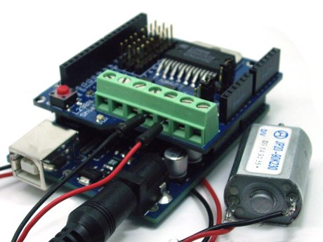
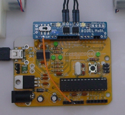
Most Arduino motor shields and the MsMot minishield from Didel use pins 4 to 7 for controlling two motors, with PWM outputs only on pins 5 and 6. Motor's drivers inputs are connected to pins 4,5 and 6,7.
Driving the motor
Let's have a motor or bicolor LED connected to pins 4 and 5. Pin 4 is set a LOW and pin 5 receive an 8-bit PWM value ( analogWrite(value) ).
Now if one wish to reverse the rotation, one need to put a HIGH on pin 4 and set the PWM value on pin 5 to be the complement of what we need. That is, if one need a low speed, a high “analog” value is required, so the difference with the HIGH of the other pin is small. The complement, 255-value , must be used as shown in next picture.
How to drive a robot with two motors
You have a robot with two motors? Make sure you understand how to control the motors with digitalWrite (on all pins) and then with analogWrite (only on pins 5 and 6). Wire you motors and define the pins with the following lines:
  #define BackLeft   4
  #define ForwLeft   5
  #define ForwRight  6
  #define BackRight  7
Define several functions to make it move:
Forward, Backward, TurnLeft, TurnRight with only one parameter. Turn left is turn on itself here. It could be turn on one wheel – test. PWM value, 0..255 must be sent on pins 5 and 6, with the good state on pins 4 and 7, depending on direction.
void Forward (int ss)  // 0-255
{
  analogWrite(ForwLeft, ss);
  digitalWrite(ForwLeft, LOW);
  analogWrite(ForwRight, ss);
  digitalWrite(RecD, LOW);
}

void Backward (int ss)
{
  analogWrite(ForwLeft, 255-ss);
  digitalWrite(RecG, HIGH);
  analogWrite(ForwRight,  255-ss);
  digitalWrite(RecD, HIGH);
}

void TurnRight (int ss)
{
  analogWrite(ForwLeft, ss);
  digitalWrite(RecG, LOW);
  analogWrite(ForwRight, 255-ss);
  digitalWrite(RecD, HIGH);
}
This is not the best way to do it though.
There are too many functions, and one cannot make smooth turns. Lets define a single function, Move(). We let the function have two parameters, the positive and negative speed for the two motors. Stop is Move (0,0), full speed backward is Move (-255,-255), etc.
| Move(left,right) function has two parameters of type int 16 bits signed. Valid values are between –255 and +255. The function test with an if statement if speed is positive or negative. Positive is easy. Local variable for left speed is named ls. For a negative speed, ls is negative, one need first to take the absolute value, -ls (-ls is positive now) and then we need to take the complement since the other side of the motor must be set at high level. \\Value is hence 255-(-ls) = 255+ls. What happens if one tries Move(500,-400); ? This will be accepted, but a speed higher than 255 will be replaced by its modulo 256 value. A solution could be to saturate the received values at the beginnng of the procedure: if (rs>255) rs= 255; if (rs<-255) rs= -255; Same for ls. | // pwm between –255 et +255
void Move (int ls, int rs) {
if (ls > 0)
{
analogWrite(ForwLeft, ls);
digitalWrite(RecG, LOW);
}
else
{
analogWrite(ForwLeft, 255+ls);
digitalWrite(RecG, HIGH);
}
if (rs > 0)
{
analogWrite(ForwRight, rs);
digitalWrite(RecD, LOW);
}
else
{
analogWrite(ForwRight, 255+rs);
digitalWrite(RecD, HIGH);
}
}
|
It is easy now to write a ballet for your robot:
Move(200,-200);
delay (100);      // turn right for 0.1s
Move(0,0);
delay (500);     // stop 0.5s

etc.
The loop to accelerate, slowdown and come back is also quite simple. Add the definitions, the set-up and the function Move() and test it.
You can use a bicolor LED in place of a real motor for testing.
The speed of change depends on the delay. Here PWM is modified by one every 8 ms. Acceleration phase lasts 256 x 8 = 2048 ms, about 2 seconds.
int v;
void loop()
{
  for (v=0;   v<255;  v++) { Move (v,v); delay (8); }
  for (v=255; v>-255; v--) { Move (v,v); delay (8); }
  for (v=-255; v<=0;  v++) { Move (v,v); delay (8); }
  delay (2000) ;
}
Have fun - JDN.
This Howto has been kindly provided by JDN from Didel SA.
Letzte Aktualisierung: © boxtec internet appliances · the better security products


