Table of Contents
Elecfreaks Starter Kit
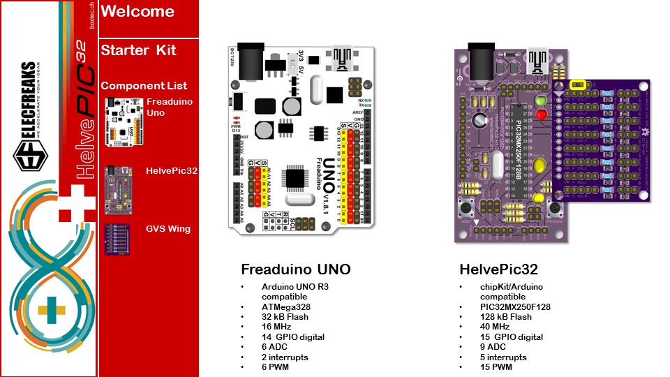
Der Elecfreaks Starterkit bietet eine leichten Einstieg in die Welt des Arduino.
Hier kann man auch sehen, wie einfach es ist, diese Module mit dem HelvePic32 zu betreiben.
Im Nachfolgenden sind die Beschreibungen als Arbeitskarten für den Arduino als auch den HelvePic32 dargestellt.
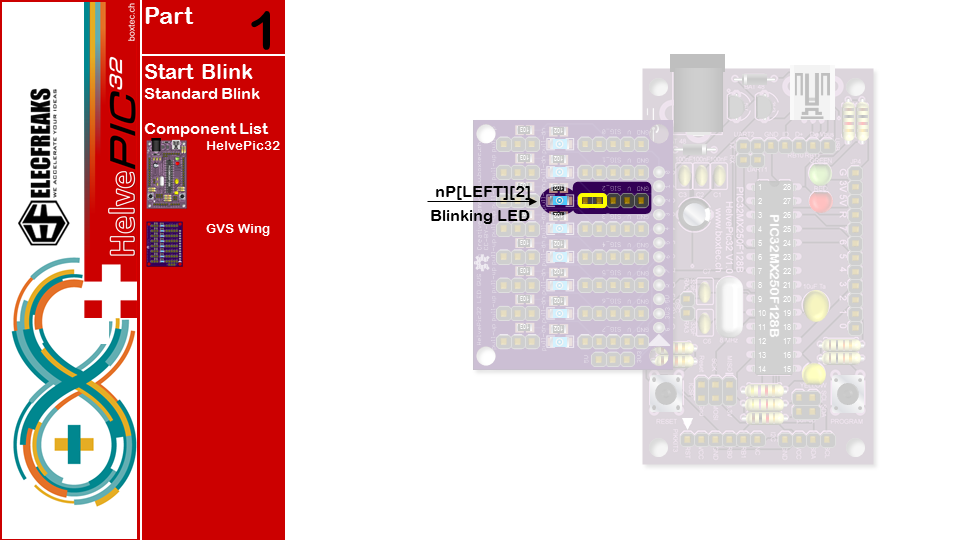
Beim HelvePic haben wir den GVSled-Wing verwendet.
Der Code kann hier herunter geladen werden, sowie die HelvePic32 Bibliothek.
/*
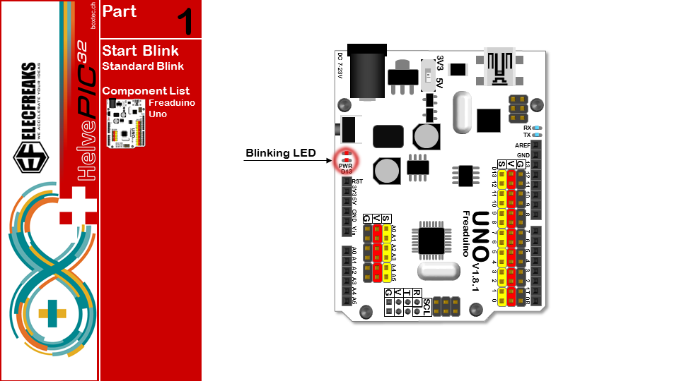
  part1  ARDUINO START
  Turns on an LED on for one second, then off for one second, repeatedly.

  This example code is in the public domain.
 */

// Pin 13 has an LED connected on most Arduino boards.
// give it a name:
#if defined(__AVR__)
int led = 13;
#elif defined(__PIC32MX__)
#include
int led = nP[LEFT][2];
#endif

// the setup routine runs once when you press reset:
void setup() {
  // initialize the digital pin as an output.
  pinMode(led, OUTPUT);
}

// the loop routine runs over and over again forever:
void loop() {
  digitalWrite(led, HIGH);   // turn the LED on (HIGH is the voltage level)
  delay(1000);               // wait for a second
  digitalWrite(led, LOW);    // turn the LED off by making the voltage LOW
  delay(1000);               // wait for a second
}
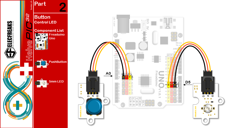
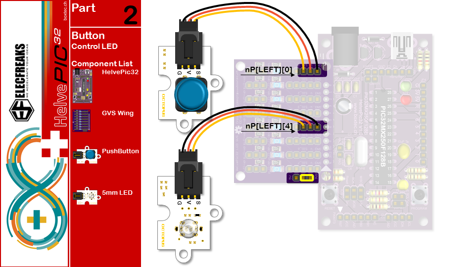
/*part2  USE BUTTON CONTROL LED
 Press the button, led lights, then press the button led is off*/
#if defined(__AVR__)
int led = 5;// The 5 pin,driving LED
int button = A0;// The A0 pin,read the button
#elif defined(__PIC32MX__)
#include
int led = nP[LEFT][4];
int button = nP[LEFT][0];
#endif

void setup() {
        pinMode(led, OUTPUT);// initialize the LED pin as an output.
        pinMode(button, INPUT_PULLUP);// initialize the BUTTON pin as an input.
}
void loop() {
        if(digitalRead(button)==LOW){
                delay(200);// wait for 200 microsecond,Avoid pressing the button and read many times in this very short time
                digitalWrite(led, HIGH);   // turn the LED on (HIGH is the voltage level)
                while(1){
                        if(digitalRead(button)==LOW){
                                delay(200);
                                digitalWrite(led, LOW);   // turn the LED off (LOW is the voltage level)
                                break;                    //End of the while loop,Back to the main loop
                        }
                }
        }
}
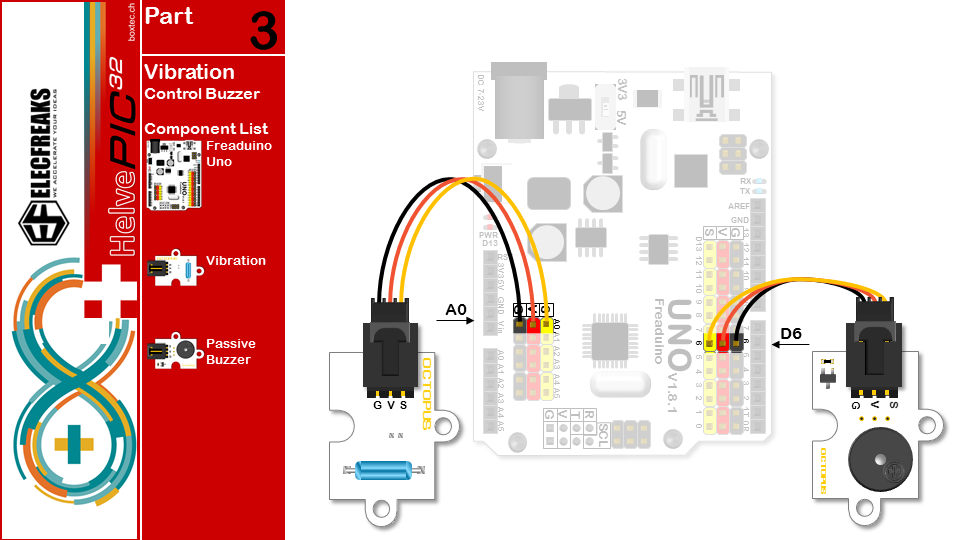
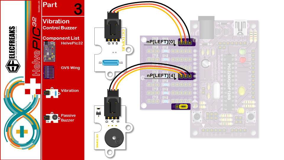
/*part3  USE Vibration sensors CONTROL Passive buzzer
 Knock on the table, the buzzer will ring */
#if defined(__AVR__)
int vibration = A0;// The A0 pin,read Vibration sensors
int buzzer = 6;// The 6 pin,driving the Passive buzzer,the pin must PWM out(3 5 6 9 10 11)
#elif defined(__PIC32MX__)
#include
int vibration = nP[LEFT][0];
int buzzer = nP[LEFT][4];
#endif
void setup()
{
        pinMode(vibration,INPUT_PULLUP);// initialize the vibration pin as an input.
        pinMode(buzzer,OUTPUT);// initialize the buzzer pin as an output.
}
void loop()
{
        if(digitalRead(vibration)==HIGH)
        {
                tone(buzzer,600,1000);
                delay(1000);
        }
}
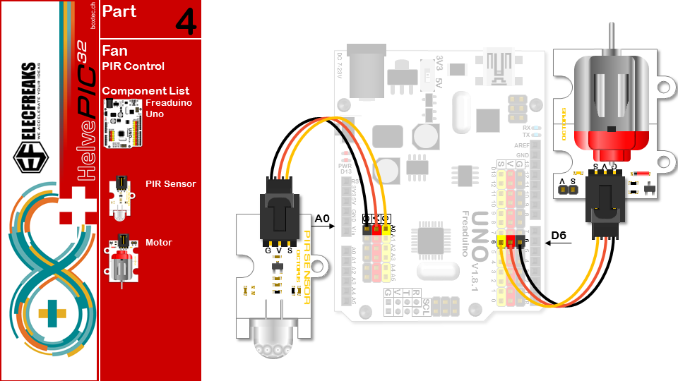
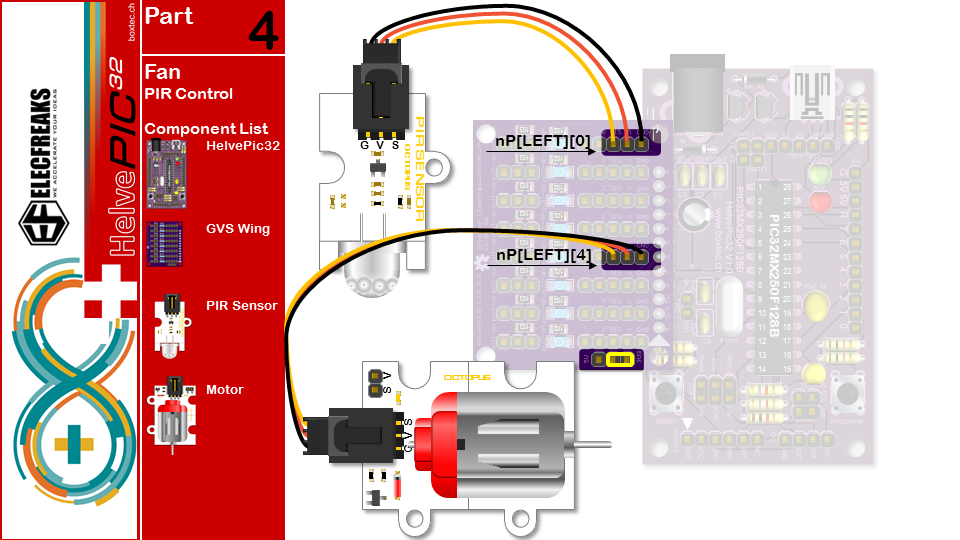
/*part4  USE PIR CONTROL Motor
 If someone passing from the front, the motor will turn */
#if defined(__AVR__)
int pir = A0;// The A0 pin,,read PIR
int motor = 6;// The 6 pin,driving the motor
#elif defined(__PIC32MX__)
#include
int pir = nP[LEFT][0];
int motor = nP[LEFT][4];
#endif
void setup()
{
        pinMode(pir,INPUT_PULLUP);// initialize the vibration pin as an input.
        pinMode(motor,OUTPUT);// initialize the buzzer pin as an output.
}
void loop()
{
        if(digitalRead(pir)==HIGH)
        {
                digitalWrite(motor,HIGH);
                delay(1000);
                digitalWrite(motor,LOW);
        }
}
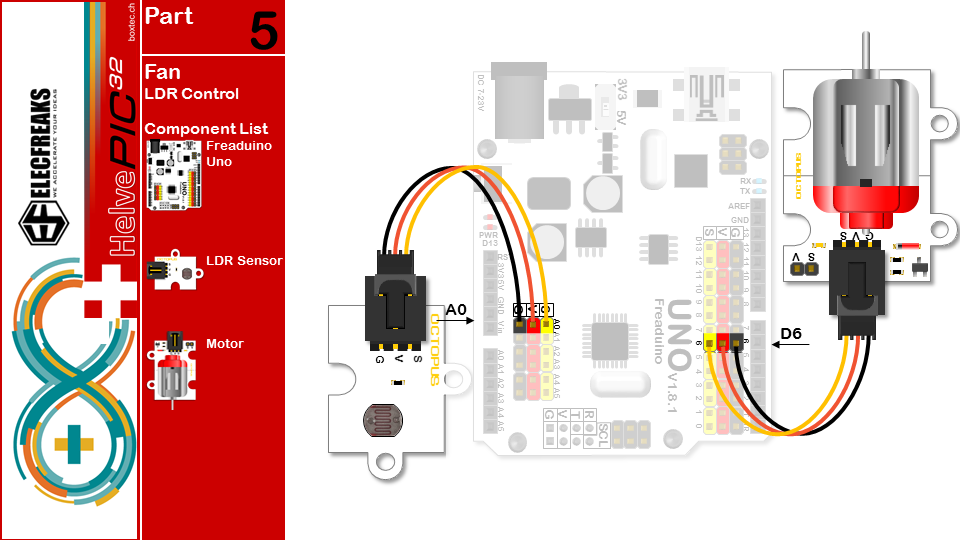
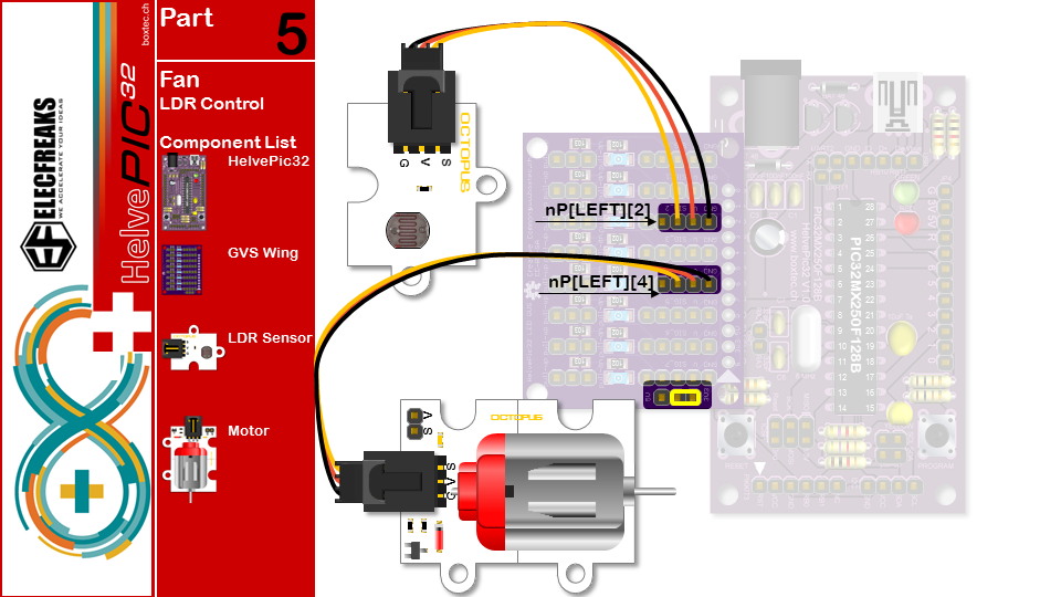
/*part5  USE Photodiode CONTROL Motor
 According to the intensity of light motor speed control */
#if defined(__AVR__)
#define myWrite analogWrite
#define MAXLDR 512
#define MAXSPD 1024
int photodiode = A0;// The A0 pin,,read PIR
int motor = 6;// The 6 pin,driving the motor
#elif defined(__PIC32MX__)
#include
#include
#define myWrite SoftPWMServoPWMWrite
#define MAXLDR 1024
#define MAXSPD 255
int photodiode = nP[LEFT][2];
int motor = nP[LEFT][4];
#endif

void setup() {
        pinMode(photodiode,INPUT);// initialize the photodiode pin as an input.
        pinMode(motor,OUTPUT);// initialize the motor pin as an output.
}                                                                                                                                                                                                                       void loop() {
        int speed=map(analogRead(photodiode),0,MAXLDR,0,MAXSPD);//because the read max value is 512
        myWrite(motor,speed);//According to the intensity of light motor speed control
}
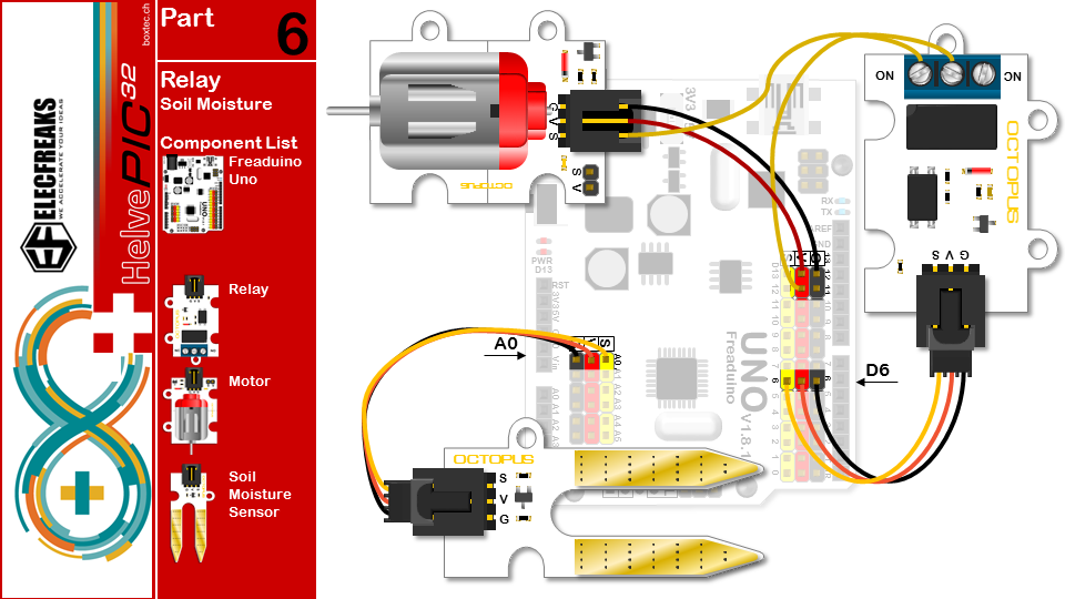
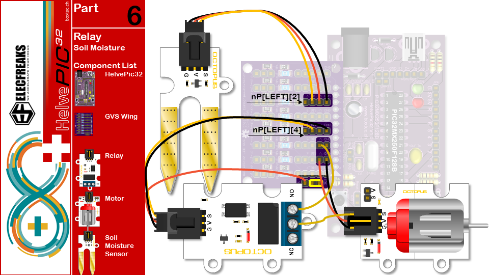
/*part6  USE Soil moisture CONTROL Relay
 According to the intensity of light motor speed control */
#if defined(__AVR__)
int soil = A0;// The A0 pin,,read Soil moisture
int relay = 6;// The 6 pin,driving the Relay
#elif defined(__PIC32MX__)
#include
int soil = nP[LEFT][2];
int relay = nP[LEFT][4];
#endif

void setup() {
        pinMode(soil,INPUT);// initialize the soil pin as an input.
        pinMode(relay,OUTPUT);// initialize the relay pin as an output.
}
void loop() {
        int value=analogRead(soil);
        if(value>200){//set the default value ,you can set it then more or less to do something
                digitalWrite(relay,HIGH);//turn on the relay
        }
        else digitalWrite(relay,LOW);//turn off the relay
}
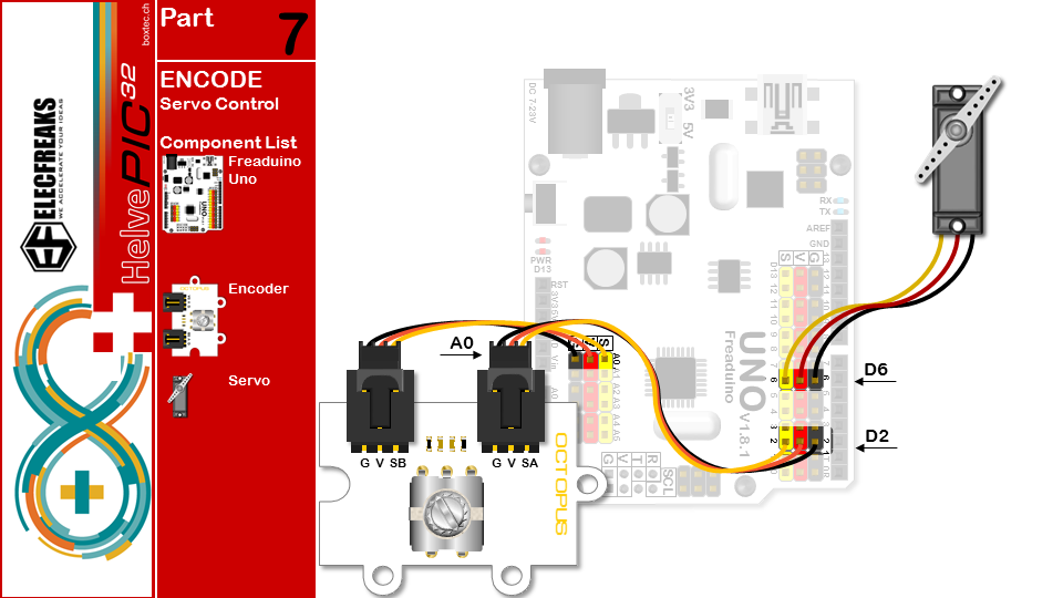
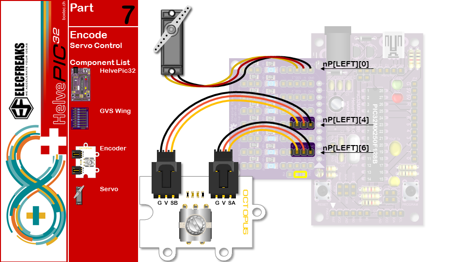
/*part7  USE encode CONTROL Servos
 Turn the rotary encoder control servos
 */
#if defined(__AVR__)
#include //load servo library
#define encodeB A0// The A0 pin,read encodeB
int servos = 6;// The 6 pin,driving the servos
Servo servo;//Get a servo controller
#define INTNR 0
#elif defined(__PIC32MX__)
#include
#include
int encodeB = nP[LEFT][4];
int servos = nP[LEFT][0];
#define INTNR 2
#endif

volatile int angle=90;//set the servo default angle

void setup() {
        pinMode(encodeB,INPUT);// initialize the encodeB pin as an input.
#if defined(__AVR__)
        servo.attach(servos);
        servo.write(angle);
#elif defined(__PIC32MX__)
        SoftPWMServoInit();
        SoftPWMServoSetFrameTime(100000);
        SoftPWMServoSetServoFrames(8);
        SoftPWMServoServoWrite(servos, 10*angle+500);
#endif
        attachInterrupt(INTNR,start,FALLING);//set encodeA interrupt,this board interrupt0 is pin 2
}
void loop() {
}

void start(){
        if(digitalRead(encodeB)==HIGH){
                angle-=3;
        }
        else angle+=3;
        if(angle>=180)angle=180;
        else if(angle<=0)angle=0;
#if defined(__AVR__)
        servo.write(angle);
#elif defined(__PIC32MX__)
        SoftPWMServoServoWrite(servos, 10*angle+500);
#endif
}
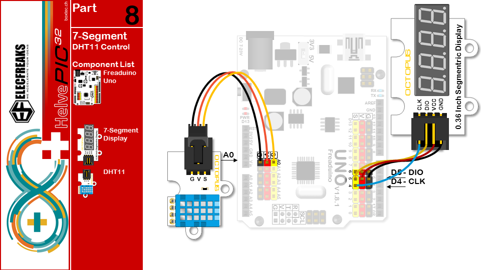
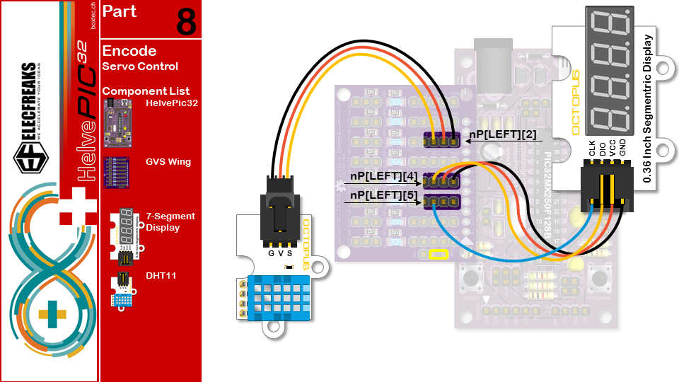
/* Part 8 USE DHT11 Temperature and humidity sensor and Segment
 * display Temperature and humidity*/
#include "DHT11.h" //load Temperature and humidity sensor library
#include "TM1637.h"//load Segment display library
#if defined(__AVR__)
#define DHT A0
#define CLK 4//pins definitions clk  for TM1637
#define DIO 5//pins definitions dio for TM1637
#elif defined(__PIC32MX__)
#include
#define DHT nP[LEFT][2]
#define CLK nP[LEFT][5]
#define DIO nP[LEFT][4]
#endif
TM1637 tm1637(CLK,DIO);//get Segment display controler
DHT11 dht11(DHT);//DHT11  A0
void setup(){
        tm1637.init();
        tm1637.set(BRIGHT_TYPICAL);
}
void loop(){
        dht11.start();
        tm1637.display(3,12);//Temperature Unit
        tm1637.display(2,(dht11.DHT11data)[2]%10);
        tm1637.display(1,(dht11.DHT11data)[2]%100/10);
        delay(1000);
        tm1637.clearDisplay();
        tm1637.display(3,(dht11.DHT11data)[0]%10); // humidity
        tm1637.display(2,(dht11.DHT11data)[0]%100/10);
        delay(1000);
}
Unglücklicherweise wurde die IRremote Bibliothek nicht zu chipKit portiert. Daher haben wir den Code hier gesplittet.
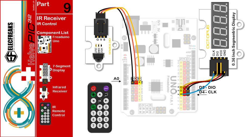
Arduino Code
/* Part9 USE IRreceive and IR remote Displayed on the segment code */
#include //load IRremote library
#include "TM1637.h"//load Segment display library
#define IRP A0
#define CLK 4//pins definitions clk  for TM1637
#define DIO 5//pins definitions dio for TM1637

TM1637 tm1637(CLK,DIO);//get Segment display controler
IRrecv ir(IRP);//an instance of the IR receiver object, IRR is IRreceive pin;
decode_results result; // container for received IR codes
long codes[10]=             // this array is used to store infrared codes
{
        0xFD708F,0xFD08F7,0xFD8877,0xFD48B7,0xFD28D7,0xFDA857, //0 1 2 3 4 5
        0xFD6897,0xFD18E7, 0xFD9867,0xFD58A7}; // 6 7 8 9
void setup(){
        tm1637.init();
        tm1637.set(BRIGHT_TYPICAL);
        ir.enableIRIn();
}
void loop(){
        if(ir.decode(&result)){
                int i=-1;
                while(!(i>9||result.value==codes[++i]));
                ir.resume(); // resume receiver
                if(i<10){
                        tm1637.clearDisplay();
                        tm1637.display(3,i);//IRremote value
                }
        }
}
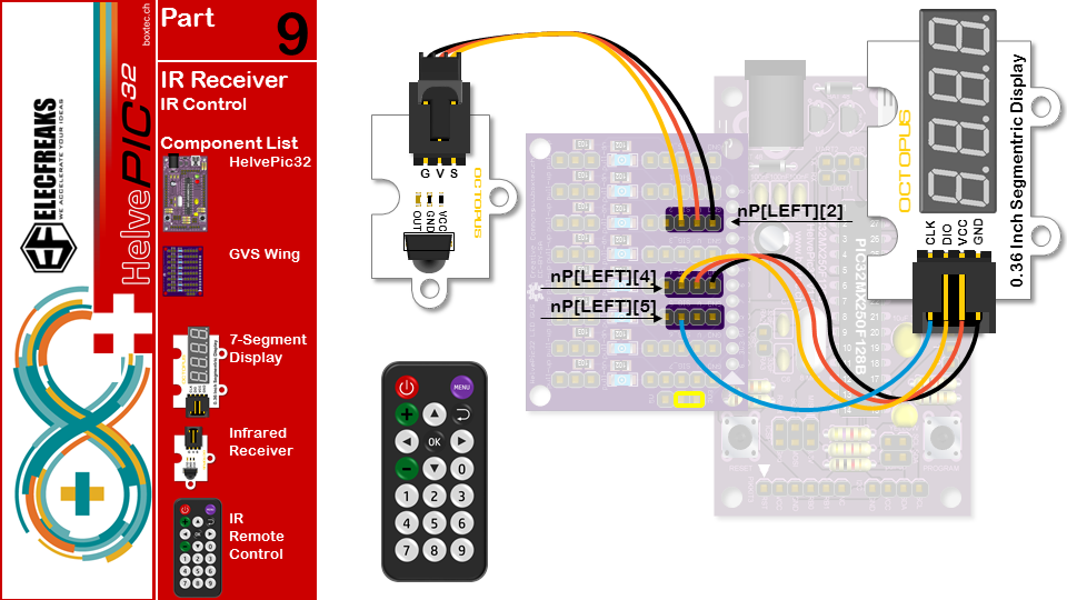
HelvePic32 Code
/* Raw IR decoder sketch! */
#include
#include "TM1637.h"//load Segment display library
#define IRpin_PIN      PORTA //PORTD
#define IRpin          0 // 8
#define MAXPULSE 65000
#define RESOLUTION 20
#define MAXKEYS 20
#define CLK nP[LEFT][5]
#define DIO nP[LEFT][4]

TM1637 tm1637(CLK,DIO);//get Segment display controler
uint16_t pulses[100][2];  // pair is high and low pulse
uint8_t currentpulse = 0; // index for pulses we're storing

void setup(void) {
        tm1637.init();
        tm1637.set(BRIGHT_TYPICAL);
        Serial.begin(9600);
        Serial.println("Ready to decode IR!");
}

void loop(void) {
        uint16_t highpulse, lowpulse;  // temporary storage timing
        highpulse = lowpulse = 0; // start out with no pulse length
        while (IRpin_PIN & (1 << IRpin)) {
                highpulse++;
                delayMicroseconds(RESOLUTION);
                if ((highpulse >= MAXPULSE) && (currentpulse != 0)) {
                        printpulses();
                        currentpulse=0;
                        return;
                }
        }
        pulses[currentpulse][0] = highpulse;
        while (! (IRpin_PIN & _BV(IRpin))) {
                lowpulse++;
                delayMicroseconds(RESOLUTION);
                if ((lowpulse >= MAXPULSE)  && (currentpulse != 0)) {
                        printpulses();
                        currentpulse=0;
                        return;
                }
        }
        pulses[currentpulse][1] = lowpulse;
        currentpulse++;
}

void printpulses(void) {
        int code = -1;
        const uint32_t CODES[] = {
                0xE21D7E00, // 0
                0xDE217E00, // 1
                0xDC237E00, // 2
                0xDA257E00, // 3
                0xD6297E00, // 4
                0xD42B7E00, // 5
                0xD22D7E00, // 6
                0xCE317E00, // 7
                0xCC337E00, // 8
                0xCA357E00, // 9
                0xF6097E00, // +
                0xE6197E00, // -
                0xF40B7E00, // up
                0xE41B7E00, // down
                0xEE117E00, // left
                0xEA157E00, // right
                0xEC137E00, // ok
                0xF20D7E00, // return
                0xFA057E00, // menu
                0xFE017E00              }; //power
        uint32_t IRid=0;
        uint8_t cnt=0;
        uint16_t p1, p2, d;
        for (uint8_t i = 1; i < currentpulse-1; i++) {
                if (i<32) {
                        p1 = pulses[i][1] * RESOLUTION/10;
                        p2 = pulses[i+1][0] * RESOLUTION/10;
                        d = abs(p1-p2);
                        if (d>20) {
                                // 1
                                IRid |= 1 << i;
                        }
                        else {
                                // 0
                                IRid &= ~(1 << i);
                        }
                }
        }
        Serial.print(IRid, HEX);
        Serial.print("  ");
        for (uint8_t i=0; i<MAXKEYS; i++) {
                if (IRid == CODES[i]) code = i;
        }
        Serial.println(code);
        tm1637.clearDisplay();
        tm1637.display(3,code%10);
        tm1637.display(2,code%100/10);
}
